A single lens, flipped around — same focal length, but a meaningfully different result. The plano-convex lens is one of the most common optical elements in any photonics lab, yet its orientation is one of the most frequently overlooked details at the alignment bench.
Most optical components are symmetric: a right-angle prism, a neutral density filter, a beamsplitter cube — it genuinely does not matter which face you point at the source. The plano-convex lens is not symmetric. It has one flat surface and one curved surface, and which side faces which beam matters more than many people realise, especially when you care about beam quality, focus tightness, or imaging resolution.
What is a Plano-Convex Lens?
A plano-convex lens has one perfectly flat surface and one outward-curving (convex) surface. This asymmetric geometry makes it particularly well-suited to two complementary tasks: collimating diverging light from a point source, and focusing an incoming collimated beam down to a point. These are arguably the two most fundamental operations in any optical system — from fiber coupling and laser beam shaping to illumination in fluorescence microscopes and excitation in optical tweezers.
Because both conjugate distances are rarely equal when you use a plano-convex lens in practice (one is typically near infinity), this lens form is specifically optimised for so-called "infinite conjugate" configurations — where one side of the lens sees a collimated, parallel beam and the other side converges or diverges.
The Orientation Rule
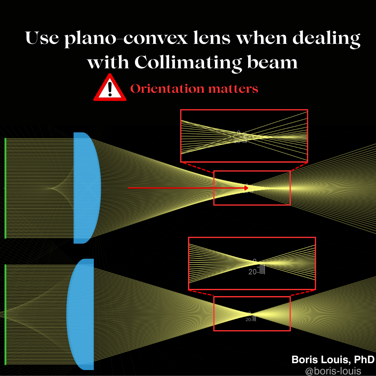
Always orient the curved side toward the collimated beam.
This rule — deceptively simple — is the heart of the matter. When the convex surface faces the collimated beam, the total refraction required to bend all the parallel rays to a single focal point is spread more evenly across both surfaces. The curved surface handles a large portion of the bending at a gentle, distributed angle of incidence, and the flat surface finishes the job with a modest contribution.
Flip the lens around — flat side toward the collimated beam — and something subtly harmful happens. The flat surface, by definition, refracts parallel rays very little (they enter nearly normal to the surface). Almost all of the bending is then delegated to the curved exit surface, which must work much harder. The steeper marginal ray angles at this single surface amplify spherical aberration, and the result is a larger, blurred focal spot rather than a tight, diffraction-limited one.
The ray-tracing simulation above illustrates this vividly. In the top configuration — curved side first — the focal region is compact and well-defined. In the bottom configuration — flat side first — the rays converge over a much wider longitudinal range, producing what opticians call a "longitudinally extended" or "blurred" focus. This is spherical aberration in its most visible form.
Why Spherical Aberration Arises
Spherical aberration occurs when rays passing through the outer zones of a lens come to focus at a different axial position than rays passing through the centre. For a single lens with spherical surfaces, this is unavoidable in principle — but it can be dramatically reduced by choosing the right lens form and the right orientation for a given use case.
The concept of lens bending — changing the radii of curvature while keeping the focal length constant — is one of the oldest tools in optical design. A plano-convex lens is already the near-optimal "bent" form for a single-element lens used at infinite conjugate. Reversing it is, in a sense, using the wrong bend for the geometry. A symmetric biconvex lens performs better when both conjugates are at roughly equal finite distances; a plano-convex lens wins when one conjugate is at infinity, but only in the correct orientation.
Practical Consequences
In everyday lab practice, the difference in orientation may seem minor — especially if your beam is small, your working distance is generous, or you are collimating rather than imaging. But as the beam diameter grows relative to the lens aperture, or as you push for tighter focusing, the penalty for incorrect orientation scales quickly. The outer rays of a wide beam suffer the most from spherical aberration, so a lens that appears fine for a small beam can cause visible degradation when the aperture is increased.
This is especially relevant in situations such as:
- Focusing a collimated laser beam to a small spot for trapping, cutting, or coupling into a single-mode fiber
- Collimating the output of a single-mode fiber or LED before a beam-shaping stage
- Simple relay imaging where one object plane is distant or effectively at infinity
- Building a custom microscope illumination path where a point source must be collimated before entering the objective back aperture
In all of these cases, the rule is consistent: curved side toward the collimated beam. The image at the top of this post, generated using the excellent phydemo.app ray-tracing simulator, makes the principle immediately concrete. I find interactive simulations like this invaluable for building physical intuition — especially when explaining optics to students or collaborators who are not yet fluent in Gaussian beam formalism.
A Quick Alignment Habit to Build
Whenever you pick up a plano-convex lens at the bench, take one second to identify the curved surface and mentally ask: where is my collimated beam? That surface should face it. If you are building a path that works in both directions — a fiber collimator that is also used in reverse to focus, for example — the rule still holds because the collimated region of the beam is the same regardless of which way light travels through your system.
It is a small detail. But in precision optical systems, small details compound. A modest increase in spherical aberration from a flipped lens can cost you coupling efficiency, degrade your point spread function, or add unwanted background in a sensitive measurement. Getting the orientation right costs nothing — flipping a lens in a mount takes seconds — and the improvement can be well worth the pause.
Frequently Asked Questions
Which side of a plano-convex lens should face the collimated beam?
The curved (convex) side should always face the collimated beam. This distributes the refraction more evenly across both lens surfaces, minimising spherical aberration and producing a sharper, tighter focal spot compared to the reversed orientation.
What happens if you flip a plano-convex lens the wrong way?
Reversing the orientation — placing the flat side toward the collimated beam — concentrates nearly all of the refraction at the curved exit surface. The steeper ray angles at this single surface amplify spherical aberration, enlarging the focal spot and degrading beam or image quality.
Can a plano-convex lens both collimate and focus light?
Yes. A plano-convex lens works in both roles: curved side toward a diverging point source to collimate the output, or curved side toward an incoming collimated beam to focus it to a point. The same orientation rule applies in both cases.
When should I choose a plano-convex lens over a biconvex lens?
Plano-convex lenses are the better choice when one conjugate is at or near infinity — for example, focusing a laser beam or collimating a point source. Biconvex lenses are more suited to symmetric configurations where both the object and image distances are finite and roughly comparable.