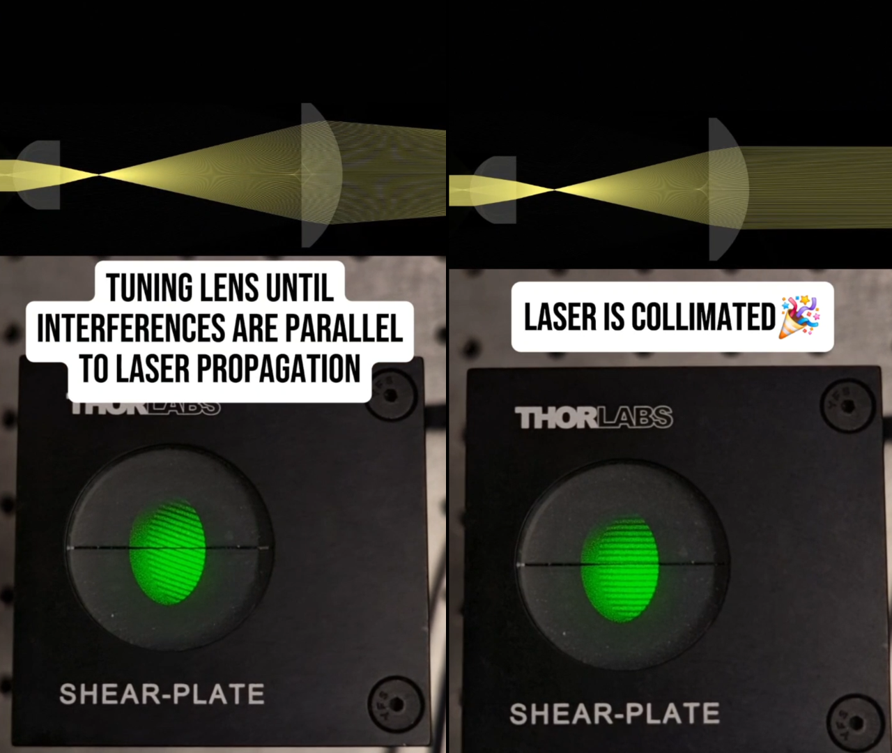
Stop checking whether your laser is collimated by eye. A shear plate does it more accurately, and in seconds — and once you have used one, going back to eyeballing a projected spot feels like guessing.
Many optical setups require expanding or shrinking a beam while keeping it collimated, or simply collimating the raw output of a laser in the first place. In each case the alignment reduces to one deceptively hard question: what is the exact lens position that produces a truly parallel beam? Judged by eye, “good enough” is often a fraction of a diopter away from flat, and that small residual curvature quietly propagates through every element downstream. A shear plate turns that guess into a direct, visual measurement.
Why collimation is harder than it looks
When you collimate by eye, you are usually watching the size of a projected spot and trying to keep it constant as it travels — or comparing it against a distant wall. The trouble is that the human eye is a poor wavefront sensor. A beam that looks stable over a metre or two can still carry enough curvature to defocus a downstream objective, shift a conjugate plane, or degrade the point spread function of an imaging system. The error is invisible where you are standing and only shows up as lost performance later, where it is far harder to diagnose.
For a microscope or any multi-lens instrument, that matters. Collimation errors accumulate. Getting each intermediate beam genuinely flat is often the difference between a system that performs to spec and one that is mysteriously soft.
What a shear plate actually is
A shear plate is, at heart, a simple interferometer — specifically a lateral shearing interferometer. It is a piece of high-quality glass with a very slight wedge. When a beam hits it, part reflects off the front surface and part off the back surface. Because of the wedge, those two reflections come back as two slightly shifted (“sheared”) copies of the same wavefront. Where they overlap, they interfere, and that interference pattern is what you read.
The whole diagnostic lives in the fringes:
- Beam collimated → the two sheared copies carry the same flat phase, so the fringes line up parallel to the reference line etched on the target.
- Beam diverging or converging → the wavefront is curved, the phase no longer matches across the shear, and the fringes tilt away from the reference line.
So the procedure is almost embarrassingly direct: tune your collimating lens or your lens spacing while watching the pattern, and stop the moment the fringes swing parallel to the reference. That is perfect collimation, reached in a couple of minutes, with no expensive wavefront sensor in sight.
Why reach for a shear plate
- Speed collimation checked in seconds, not by trial and error over a long throw distance
- Accuracy sensitive to residual curvature the eye cannot resolve
- Simplicity a single passive optic — no electronics, no calibration, no software
- Reproducibility the "parallel fringe" condition is objective and repeatable across sessions and users
Aligning a multi-lens system
The single-lens case is easy. Real instruments have several lenses in series, and there the shear plate becomes a genuine workflow rather than a one-off check. The trick is to align lens by lens, always feeding each stage a known input:
- Set the input. Tune the light going into the lens you are aligning so that, if that lens is correctly positioned, its output should be collimated. Depending on the design, that input is itself either collimated or has a defined divergence.
- Drop in the shear plate. Place it in the output beam and adjust the lens until the fringes go parallel.
- Move to the next lens. Return to step one for the following element, using the now-collimated beam as the reference.
Working through the system this way keeps errors from compounding: each lens is verified against a clean input before you rely on its output. In practice this made my own alignment noticeably faster and, more importantly, more reproducible — I could return to a setup weeks later and land on the same condition.
Where a shear plate stops working
A shear plate is elegant precisely because it is passive and simple, but that simplicity comes with real limits worth knowing before you trust it.
The method depends on interference between the two sheared copies of the wavefront, so the source needs a coherence length long enough to bridge the shear. Continuous-wave and long-coherence lasers are ideal; short-pulse lasers, with their broad spectra and short coherence lengths, may produce weak or no fringes.
Two further practical points come up often:
- Infrared beams. A shear plate works perfectly well in the IR — the physics does not care about wavelength — but you cannot see the fringes directly. You need a visualisation method, such as an IR viewer card or a detector, to read the pattern.
- Quantification. For most alignment work, “make the fringes parallel” is all you need and reading it by eye is enough. If you want a number, you can measure the orientation and spacing of the fringes with a high-resolution linear detector, which turns the qualitative check into a quantitative one. A Shack–Hartmann sensor is a more capable but considerably more expensive alternative if you need full wavefront characterisation rather than a simple collimation check.
The takeaway
A shear plate is a small, inexpensive tool that punches far above its price. It replaces a subjective judgement — is that spot the same size over there as it is here? — with an objective, visual condition you can converge on in minutes. For anyone building or maintaining optical systems, from a single beam expander to a full microscope, it is one of the highest-leverage additions you can make to a bench. Know its limits around coherence and visualisation, and it will make your alignments both faster and more reproducible.
If you align beams regularly, the interesting question is what you reach for instead — projected spots, autocollimators, a full wavefront sensor — and where each one earns its place.